of Special Equipment
Mobile cuttings dryer MK 1200-K-40-Ts-KhL1-0
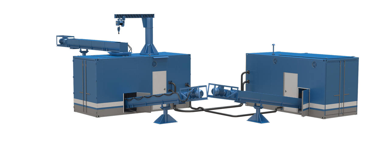
The mobile cuttings dryer is a set of equipment designed to separate cuttings into solid (dry cuttings) and liquid (centrifuge centrate) phases. The complex includes two blocks of the type of a 20-foot container, made in the Arctic version, for the possibility of operating the equipment in the regions of the Far North.
The principle of operation of the equipment
The main element of the mobile cuttings dryer (hereinafter referred to as MCD) is a vertical sludge dryer unit located in the first container (hereinafter referred to as the VD unit), for the subsequent treatment of the centrifuge centrate, a horizontal centrifuge unit is used located in the second container (hereinafter referred to as the HC unit). The units are interconnected by technological lines. Dry sludge is removed using screw conveyors of various lengths (the length of the working part of the conveyor is agreed with the Customer).
Description of the operation of the VD unit
The VD unit is made according to the type of a 20-foot anti-vandal container with insulated walls of the "sandwich panel" type, at least 100 mm thick.
The maximum overall dimensions (L x Wx H) do not exceed 6058 x 2540 x 3080 mm, which allows the equipment to be transported by road on federal roads without restrictions. For the convenience of dismantling the equipment, in addition to the swing gates on the end sides, the unit also has a removable roof section (Appendix 2).
After separation of the liquid and solid phases by a vertical dryer, centrate enters the receiving tank. To prevent centrate freezing, an explosion-proof electric heating element is placed in the tank. The tank is equipped with a paddle mixer, a cleaning hatch and a maintenance hatch. To collect leaks, the floor is sloped towards the eco-pallet.
Hydraulic piping of the VD unit allows to:
- pump centrate from the accumulative tank by screw pumps to the HC unit to a horizontal centrifuge;
- supply centrate to the inlet of the vertical dryer to dilute the incoming sludge.
To dismantle the screen panel of the vertical dryer, the hinged doors equipped with gas lifts are provided in the upper part of the unit. The screen panel is lifted using a cantilever-slewing crane with a lifting capacity of 1 t.
Composition of the VD unit
|
Description |
Quantity, pcs. |
|
Container 20ft |
1 |
|
Sludge dryer |
1 |
|
Screw pump No. 1, No. 2 |
2 |
|
Storage tank, 3 m3 |
1 |
|
Mechanical paddle mixer PBRT-40-GK-1100-22-900-turbo (engine power - 4.0 kW) |
2 |
|
Auxiliary control cabinet |
1 |
|
Hydraulic piping |
1 set |
| Axial exhaust fan, VO 06-300 No. 3.15 V (V1), version 2 0.18 kW, 1500 rpm | 2 |
| Heat gun, explosion-proof air heater NOSOROG 380-35-50-9, power - 9 kW | 3 |
|
Fire smoke detector |
1 set |
|
Gas analyzer |
1 set |
|
Explosion-proof jib crane, capacity 1t (U1 location category) |
1 |
|
Screw conveyor for sludge feeding, 8 m (working length) |
1 |
|
Screw conveyor for sludge discharging, 12 m (working length) |
1 |
|
Liquid level sensor with light signaling |
1 set |
|
Lighting equipment set |
1 set |
|
Portal for maintenance and repair of the vertical dryer |
1 |
|
Technological line for connecting units of the installation |
1 set |
|
Roof railing |
1 set |
|
Power cable of the required section, complete with a socket |
100 m |
|
Electricity consumption metering unit |
1 set |
Description of the operation of the HC unit
The HC unit is made in the form of a 20-foot anti-vandal container with insulated walls of the "sandwich panel" type, at least 100 mm thick.
The maximum overall dimensions (L x W x H) do not exceed 6058 x 2540 x 3050 mm, which allows the equipment to be transported by road on federal roads without restrictions.
Depending on the need, the design of the unit allows to place screw conveyors on two opposite sides of the block. For the convenience of dismantling of the equipment, in addition to the swing gates on the end sides, the unit also has a removable roof section (Appendix 3).
The centrate from the HC unit enters a horizontal centrifuge, which removes sludge with a low specific gravity from the solution. The purified solution enters the storage tank with a volume of 2.5 m3. The tank is equipped with a paddle mixer, a cleaning hatch and a maintenance hatch. To prevent centrate freezing, an explosion-proof electric heating element is placed in the tank. To collect leaks, the floor is sloped towards the eco-pallet.
The hydraulic piping of the HC unit allows to simultaneously pump the solution:
- from the storage tank with screw pumps to the tank of the vertical dryer in the VD unit for diluting of the centrate;
- into the line for flushing the annular space of the vertical dryer;
- to the capacitive park of the drilling rig.
The composition of the HC unit
|
Description |
Quantity, pcs. |
|
Container 20ft |
1 |
|
Horizontal centrifuge with variable frequency drive and control cabinet |
1 |
|
Screw pump No. 3, No. 4 |
2 |
|
Storage tank, 2.5 m3 |
1 |
| Mechanical paddle mixer PBRT-40-GK-1100-22-900-turbo (engine power - 4.0 kW) | 1 |
|
Auxiliary control cabinet |
1 |
|
Hydraulic piping |
1 set |
|
Axial exhaust fan, VO 06-300 No. 3.15 V (V1), version 2 0.18 kW, 1500 rpm |
2 |
| Heat gun, explosion-proof air heater NOSOROG 380-35-50-9, power - 9 kW | 2 |
|
Fire smoke detector |
1 set |
|
Gas analyzer |
1 set |
|
Lighting equipment set |
1 set |
|
Screw conveyor for cuttings, 8 m (working length) |
1 pce |
|
Electricity consumption metering unit |
1 set |
|
Power cable of the required section, complete with a socket |
100 m |
General installation requirements
The execution of all units, assemblies, fencing and piping complies with federal norms and rules in the field of industrial safety "Safety Rules in the Oil and Gas Industry".
The quality of paint coatings must comply with class VI according to GOST 9.032-74, the operating conditions group - VI according to GOST 9.104-79 (mineral oils and lubricants, gasoline, kerosene and other petroleum products). The thickness of the complex paintwork is 90 - 110 microns, the primer layer is 40 - 50 microns, the top coat is 50 - 60 microns.
Flow parts of pumps, seals, valves and connecting elements of pipelines are made in oil and petrol resistant design.
Power supply of the equipment is carried out from the alternating current network with a voltage of 380 V, 50 Hz. All electrical equipment is supplied as explosion-proof. Explosion protection class - Exd II BT4.
The electrical equipment used complies with the regulatory documents in force on the territory of the Russian Federation, namely: GOST 12.2.007.0-75, GOST 14254-2015, TR TS 012/2011, PUE, Ch. 7.3, PUE, Ch. 7.4, GOST R MEC 60079-31-2010, GOST IEC 60079-1-2011, GOST R MEC 60079-7-2012, has the necessary certificates of conformity.
|
Parameter |
Value | Notice |
|
Overall sizes of the unit (LхWхH), m |
9 х 9 х 5 |
Excluding screw conveyors |
| ГUnit overall dimensions in working condition, m | 20 х 9.5 х 5.7 |
Including screw conveyors |
|
Total power consumption of the VD unit, kW |
max,130 |
|
|
Total power consumption of the HC unit, kW |
max, 95 |
|
|
Power consumption |
380 V, 50 Hz |
|
|
Dryer performance, t/h |
20-30 | |
|
Horizontal centrifuge performance, m3/h |
30-45 | |
|
Screw pump performance, m3/h |
4.0 - 40 | |
|
Total weight of the VD unit, t |
max, 14 |
|
|
Total weight of HC unit, t |
max, 13 |